Hey, you in the mood for an electronics-heavy, hardware hacking post? Who cares, my blog my rules. Anyway: lotta words and science and eventually pictures, I promise, but it’s nerds all the way down from here.

Okay, I gotta at least sum up the background of this post: I’ve been playing around with a device called a Photon, made by a company called Particle. It’s a tiny little microcontroller device that seriously blurs the line between the “programmable ICs” I played with a decade ago and, well, computers. It’s the size of my thumb, costs less than $20, and its killer feature is an onboard Wi-Fi radio. They’re at https://particle.io. Go buy one, I’ll wait.*
* Disclaimer: While I have received a free Photon from a friend who works at Particle, I also bought a handful of them on my own, and Particle probably doesn’t want me writing a review for them anyway, honest or otherwise, and in fact are no doubt reading this with an increasing sense of dread. (Plus I bricked the free one right out of the gate. I’m just saying.) My opinion, which is possibly biased, is that you should buy a bunch of them. They’re awesome.
So with all that summed up, I can now move on to the problem I’ve had all week with it: I want to drive a super-bright LED module with my Photon. Seems pretty straightforward, right? With my Teensy USB (another cool product, go buy some of them, too!) I could just push current out to the red, blue or green pins of the LED module and it would light up. It is worth noting that the Teensy was a current-bearing** beast. It could shovel 80mA of current out of each pin at 5V without even getting warm. Well, without getting hot. Well, without burning the house down at any rate–look, the point is this module will take a full watt of power and the Teensy could deliver it easily.
** ampiferous? Heh. Shut up that’s an awesome word right there
Enter the Photon.
This thing is unrelentingly awesome, I won’t hear a word otherwise. One of the great features is that it runs on a super-low power budget. It runs on 3.3V (even though it will accept 5V). This means I can plug it straight into USB (5V) and it runs just fine. But those pins only spit out 3.3V. And to make matters worse, it’ll only give 25mA per pin and 125mA overall. It has a lot of love to give, but not a lot of power: 82.5mW per pin means that even with a pin driving each LED separately, it puts out less than a quarter of a watt.
But wait! My LED module has tiny little load switching transistors on it! You plug the board into 5V and ground, and then you just signal which LED you want to light up. All the drive power comes directly from the power rail, not the microcontroller… less than a tenth of a watt, in fact! Yay!
So how come, when I hook it up, the LEDs barely glow? Where my photons at, Photon?
It’s not the Photon. It’s the module. The LED module is a Sparkfun 11588 Tri-Color Breakout. This is a fun little kit you assemble yourself, and more importantly everything is easily understandable as you build it. In order to drive the LEDs, you build a circuit that is very easy to follow and understand: you drive a little current into the base of the transistor, and the collector responds by pulling down big current from the 5V power supply and dumping it through a resistor and the LED before returning to ground. More current means more light. It’s simple, it’s straightforward, it’s comprehensible.

It’s also not the best design for many applications. It was great for what it did, mind you; it just doesn’t adapt well to changing requirements. This circuit has what is called “High-Side Drive”, meaning the transistor (which “drives” the circuit) is connected to the 5V side. If we took the transistor out and moved it down next to the ground side, it would be called “Low-Side Drive”.
Why does this matter? Well… okay, TL;DR it just does and if you don’t want a longer explanation skip to the next paragraph. The longer explanation is this: I don’t actually know. Man, I sure hope you skipped this part. What I think is happening is that with 3.3V on the base and 5V on the collector, a 1.7V volt drop is created across the Collector-Base junction (Vcb for you electronics nerds), artificially limiting the output from the transistor. Normally a transistor can be thought of as an entirely current-based device, but in this case the transistor is forced to throttle the flow all the way back until a 1.7V drop is maintained from the 5V rail down to the 3.3V signal.
Now, there are a few ways you could fix this problem. The first is to alt-tab over to Adafruit and buy a 3.3V to 5V signal converting chip. They’re like $1.50, no biggie. You’d pay more in shipping than you would for the hardware, though, and if you’re like me–and this example you are–you’re gonna throw ton of other in your cart, so that chip is going to set you back closer to $50.
A second option is to dig around in the garage for some old reed relays you have lying around in an old junk parts drawer full of electronics components. You have one of those, right? Hey, me too! So you wire up the Photon to open and close the relays, and the relays switch the 5V supply directly to the signal pins on the module. Check it out:

Oh, wait, sorry. I said it was bright. (Fun fact: I have never seen my cell phone create an internal reflection like this before.) Here, let me turn it off.

There we go. Now this circuit works and all, but it still leaves something to be desired. I can switch the relays on and off, but that’s all I can do: turn the lights on–all the way on–or all the way off.
You can dim LEDs from a digital circuit if you turn it off and back on really fast. You shut it off and then back on before the eye can see the flicker. Do this over and over really fast, and it looks like the LED is getting darker. This trick is called pulse width modulation, or PWM. But to trick the eye, you gotta send these pulses out super fast, and those poor little relays have no chance of keeping up: they contain actual, physical, mechanical switches that are controlled by magnets. (No, I don’t know how magnets work. Yes, I am Mormon. NO, I really don’t know how magnets work. Please stop asking.) The point is, because they’re mechanical devices, they can’t switch on and off faster than you can see. We need a way to switch them on and off electronically.
A third option is to call your friend Kevin (you have a friend named Kevin, right?) who is really good with tools and insanely good at electronics (MY friend Kevin is, too–this is getting weird). He’ll tell you that you can use a 74HCT240 CMOS/TTL buffer, which is a chip that looks exactly like the one you were gonna get from Adafruit, and does exactly the same thing, but has been around for years and years–certainly long before 3.3V computing ever existed. More importantly, he can come to your house on Saturday and bring you one of these chips out of his electronics parts bin.
Cool! So you’ve got a free part coming, now you just have to wait…
Yeah, me either. Time for a fourth option. Let’s head back out to the garage. Do you have a can of solid-state relays left over from when you were manufacturing audio cutout boards for vibration control computers? No? Thank goodness, that would have been way too freaky. Anyway, I DO, so I went ahead and grabbed some.
Just one problem. They’re left over from building computer parts, parts which I built in this millennium. That’s a problem because computers nowadays use all SMT stuff: surface-mount technology. When I used these SSRs, I would etch a flat circuit board, hold the chip where it was supposed to go, then wash hot solder over the feet to make it stick to the copper. Those little feet have big flat pads on them so they can stick, and that means they don’t have the spiky pokey feet I need to jam them into my prototyping breadboard. If only I had some way of attacking wires to the SMT pads.
So, anyway, last night I sort of crafted an unholy abomination of electronics.
(That’s option four: “craft an unholy abomination”.)
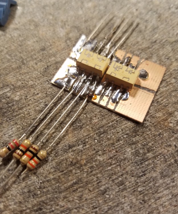
The SMT chips need a flat board to stick do, and the prototyping board needs wires or leads. So how about a board with wires on it? This is a real thing you can get professionally, called a breakout board. I don’t have one, but I do have a lot of parts…
I grabbed an unetched circuit board and cut it down to size. I don’t have any etchant, but that’s okay. There are plenty of… decidedly mechanical… ways of removing material. Marked off the little SMT pads, and started scratching a channel before I realized I needed to be taking pictures of what is no doubt going to become a triumphant abomination.

I ditched the knife and got out my handy dandy Dremel tool and the tiniest burr head I could find for it.

Okay, time to slap some solder on there. It’s been 10 years since I’ve held a soldering iron, and all I can say for this solder job is that I did not, at any point, try to hold the iron by the burny ouchy end.

Okay, halfway home. Now it’s time to give this little breakout board some legs that can go into my prototyping board…

If you’re looking at this and jumping up and down and shrieking “SOLDER IS NOT GLUE” you probably need to work on your impulse control. You’re not wrong, mind you, but dude. Settle down. People are staring.
I’m not gonna lie, soldering is NOT like riding a bicycle. Shaky hands, cold joints, poor temperature control, good times. Here’s the finished product in all its lumpy abominationy glory:

I bent the legs under and then down, so that the legs could squeeze the circuit board because solder is not glue I get it shut up already.

And there we go. Just about ready to plug straight into a circuit board!
Oh, but one last step before we plug it in. Solder is not glue, but you know what IS a good glue?

Actual glue.
And now, the moment of truth! I’m so excited! I take it to my breadboard and plug it in, and…

…nothing. No circuit, no blinking, no flickering, no joy. Completely dead. The above picture was taken between blinks on the little Photon board, so you can’t tell that it is turned on and trying to drive the LED board.
I checked the circuit very carefully for continuity faults before plugging it in, so what could OHHHH MAN.
Fun fact about CMOS chips, which these SSRs are made out of: If you handle them without static protection, especially in a dry house in Utah in October, you will fry them.
See? NOT like riding a bicycle at all.
Ugh.
LOL.
LOL! No seriously, LOL. This was a lot of fun. Not every story has to end with an epic win to have a happy ending. In this case, I got some practice soldering, and got to remember that there’s a fair bit of skill involved there. The whole time I was soldering the smell of the rosin flux burning off the iron transported me back to my teens, where I spent hundreds of hours hunched over a crappy little Radio Shack 5W iron, putting together (and tearing apart) radios, amplifiers, oscillators, power supplies… any number of crazy projects, just for the fun of doing it. I’m happy I did it and will always treasure OH OF COURSE I GOT IT WORKING BECAUSE YES AN EPIC WIN IS REQUIRED IN THIS INSTANCE.
Let’s talk about option five. I sort of hinted at it accidentally when I was describing the problem earlier. So the original SparkFun design is flawed because it is high-side driven. If we could somehow change this circuit to be switched from the low side… well, ground is zero volts, whether your circuit is 5V or 3.3V. If we can ground one circuit, we can ground any circuit.
I don’t have a schematic drawing of a Low-Side Drive circuit, but if you look at the circuit at the top of this post, the circuit you want can be created by turning it upside down. The 5V comes in and hits the LED, then goes through the resistor, then through the transistor, and out to ground. Heck, I don’t even have to change the circuit board!
Well, okay, not the board itself anyway… readers familiar with electronics will realize that you can’t just run electricity backwards through a diode. That’s, like, a diode’s entire job in electronics, to keep you from doing just that.
So I desoldered the diodes, flipped them around backwards, and soldered them back in.
Transistor? Same problem: current won’t flow up the emitter and out the collector. Same solution: desolder, flip them 180°***, put them back in.
*** That’s 82.2°C in metric
This was a lot harder to do than it sounds. Fortunately, I never had a lot of money for electronics, so I always got most of my parts by scavenging existing circuitry. Here’s a #ProTip for you: remove the component before you remove the solder. You can jam the iron in so that all of the solder joints melt at once, and the parts slips out easily before taking heat damage. Then you can mop the solder out of the joints with a solder sucker or desoldering braid.
Here’s what the module looks like with diodes and transistors reversed:

You can’t really tell with the LEDs, but the transistors have their flat sides facing backwards from the little white outline on the circuit board.
Another fun fact is now I have to remember to always hook VCC and GND up backwards. There is something so perversely satisfying about that. It warms the filthy cockles of my gross disgusting heart.
And now, the question: does it work?
Well, at full power it looks about like the first photo of the board way back at the top of this post. But what if we tell the Photon to drive each LED at a different amount of power? Well… now that’s a different story:

Pay more attention to the bar graphs than the numbers; A5 and A3 have different PWM timers, and for some reason one goes to 256 and the other to 4096. (A5 might actually be a true DAC, I’m not sure. But A3 is definitely PWM.)
So… there you have it. High-side drive is a pain, low-side drive is awesome. Ground is ground is ground. and if your circuit has HSD, you need to use LSD to see all the pretty colors.
You heard me.
